
At our last meeting, we found four feedlines in the shack and wanted to know what might be on the other end of each of them. We hooked up each feedline in turn to a software radio receiver and viewed a frequency-domain plot (signal strength vs. frequency). We measured the strength of the noise floor, which is the “ ‘no signal’ signal” – what you measure when there’s nothing being broadcast. The noise floor signal strength is a decent indicator of what might be connected. For each of three different frequencies, we measured the noise floor with no antenna connected, and then measured the noise floor with each of the four antennas in turn.
The antennas are colour-coded by the pieces of electrical tape we put on the feedlines. The yellow and blue feedlines were indistinguishable from having no antenna connected. The red one was a little bit more interesting, especially around 146 MHz, but the green feedline raised the noise floor significantly. This suggests that there may be something hooked up to the green cable.
To test how well the feedlines could receive a real signal, we used a low-power transmitter to broadcast a test signal at 147 MHz and measured the strength of that one signal through each feedline. The green feedline performed best, receiving the signal at -40dB (which is a very strong signal); the red one was about 10dB weaker, and the yellow and blue almost indistinguishable from having no antenna at all. The fact that we observed a stronger signal with the green feedline than with any of the others strongly suggests that there is some kind of antenna connected to it.
We did a final test to measure the noise floor on the green feedline around 58 MHz (the closest the receiver can get to HF bands) and saw that it was -65 dB. This is pretty good, and so we hypothesized that our large HF antenna might be connected to it.
Now I’d like to present some new results that I measured today, which seem to suggest a different picture of things.
I did a test with a device called an “upconverter” that receives radio signals and shifts them up to a higher frequency. The purpose of it is to allow devices that can’t normally receive low frequencies (such as anything on HF) to be able to tune to some upconverted frequency and hear the signals that would be present at the lower frequency. For the upconverter that I have, if you want to hear signals broadcast at a frequency ‘f’, you tune your receiver to 125 MHz + f.
The reason I did this was to test the best-performing feedline on HF, which normally our software radio receivers cannot access at all. However, through the upconverter I was able to tune it to a few different frequencies on HF, and the results were interesting.
Here’s what the spectrum looks like around 10MHz on the green feedline:
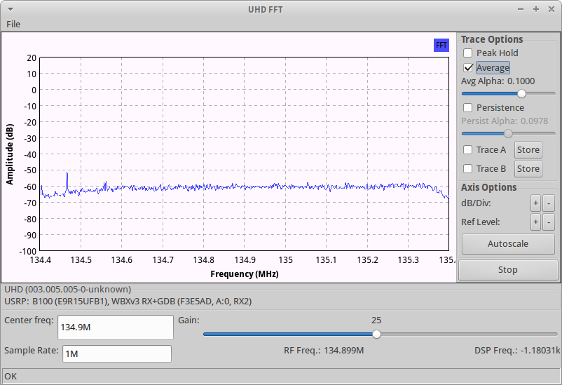
Now, this was a surprising result, because I was convinced I knew which antenna was connected to this feedline. From the tests we did on Friday, the results suggested that this antenna would perform really well on HF. However, the spectrum analysis shows almost pure noise here, which is actually not what we expect! The reason I chose this part of the band is because there is a very powerful time signal broadcast from a station called WWV on exactly 10MHz. I looked for that on the spectrum, but on the green feedline it’s not there. Same thing happened at a few different frequencies – normally on HF there’s going to be quite a bit of stuff going on at any one time, but we’re not really receiving anything through this feedline.
That’s when I remembered that a while ago, we found a fifth feedline. We’ll label it “white” because the white electrical tape was the only unused colour. Of course, this one wasn’t included in our initial tests, so I skipped right to testing on HF and saw this spectrum immediately:
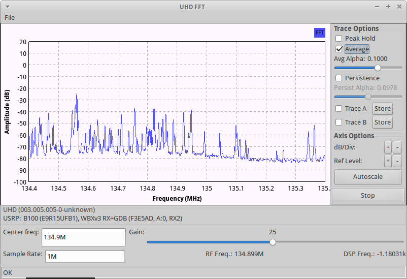
Now THAT is what HF should look like. Notice the strong signal right at “135” (125 + 10MHz, don’t forget) – that’s the WWV time signal we couldn’t hear before on the green feedline.
So I tuned around a bit more and, basically, the white feedline leads directly to our really big antenna for HF on the roof. None of the other feedlines even came close to this.
But that still doesn’t explain what happened with the green feedline, which performed really well. We suspected that something was connected up there, and thought it was the HF antenna, but that was ruled out – green couldn’t receive HF at all. To test the green feedline, I used a low-power transmitter to broadcast a test signal on each of 3 frequencies, and compared it to what we could receive with no connection, with the white feedline, and with a “known good” reference antenna that is specifically designed for reception on that frequency.
For a test signal at 147 MHz: the white feedline received it about as well as when no antenna was connected (-80dB); the reference antenna did well at -30dB; and the green feedline got -40dB as before.
I tested again at about 465 MHz: the white feedline again did as well as having nothing (-70dB); the reference antenna received at -33dB; and the green feedline was close at -45dB.
I tested a third time at 1275 MHz. The white feedline was surprisingly better than nothing (-80dB vs. -95dB), but the reference antenna and green feedline did two orders of magnitude better at -60dB.
Now, there’s a very good reason why, for both the noise floor and transmission tests, I chose these three frequencies. Earlier while cleaning the shack, we found a rolled-up container for an antenna that we knew was on the roof – a Diamond X6000. This antenna is tuned for exactly the bands in which we made these tests. The theory was that if a feedline offered a significant improvement over having nothing connected, this antenna was probably on the other end.
I did one more test after I went home. I left the green feedline hooked up to the receiver and accessed it remotely from my room. I used my handheld to transmit a test signal on 147 MHz and on 465 MHz. Because the receiver I was using has two external connectors for a receiver, I left one of them disconnected and switched back and forth between them remotely while transmitting. With no feedline connected, I couldn’t hear anything. With the green feedline selected, I was able to pick out the signal I was transmitting – from home – 30dB above the noise floor both times.
So, with this new information available, I think a better picture of things is this: the white feedline is connected to our large antenna for HF, and the green feedline is connected to our tri-band antenna for 144/430/1200MHz.
But I still want to test those other three feedlines, just in case…